Edit Sheet Metal Material Gauge
How To Drive Sheet Metal Parts Kb12121018 Driveworks Documentation
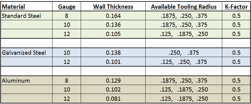
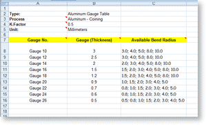
How To Set Up Sheet Metal Gauge Tables Engineers Rule
2019 Solidworks Help Sheet Metal Gauge Tables

Solidworks Sheet Metal Gauge Table And Properties Youtube
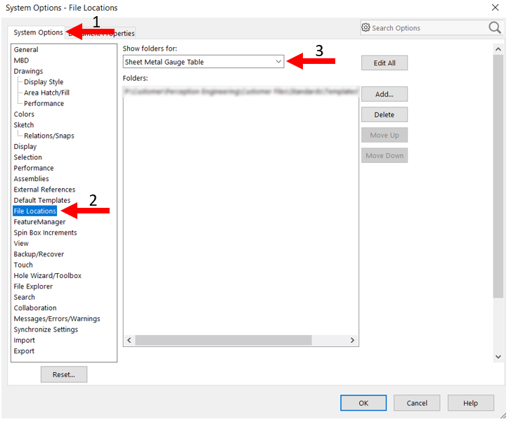
Solidworks Sheet Metal Gauge Tables Perception Engineering

Steel Thickness Chart Sheet Metal Tools Metal Working Welding Classes
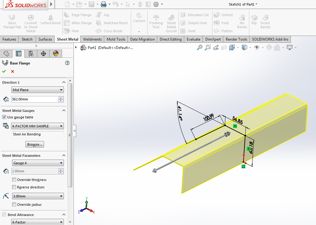
While creating the base flange from the base flange propertymanager.
Edit sheet metal material gauge.

How To Convert Thickness Into A Solidworks Sheet Metal Gauge Value

Charter Meaning In Hindi Aluminum Gauge Thickness Conversion Chart Steel Weight Nextbook Co Editor Sheet Metal Tools Metal Working Welding Classes

How To Create A Custom Solidworks Sheet Metal Bend Table
Sheet Metal Success In Solidworks Engineers Rule
2018 Solidworks Help Bend Table

Sheet Metal Gauge To Mm Gauge To Thickness Chart Download Sheet Metal Is Metal Formed By An Industrial Process Into Sheet Metal Gauge Metal Gauge Sheet Metal

Solidworks Unlocking Properties In Sheet Metal Parts
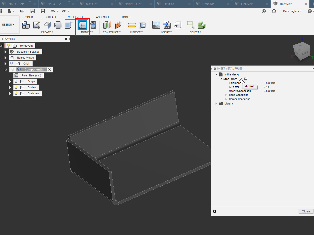
Solved How To Change Thickness Of Steel Autodesk Community Fusion 360

Print Decimal Chart Gauge To Decimal Conversion Chart Stainless Sheet Strip Galvanized Decimal Chart Sheet Metal Gauge Conversion Chart
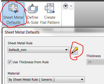
Setting Sheetmetal Thickness Autodesk Inventor Autocad Forums

Auto Vs Corner Relief In Solidworks Sheet Metal

Steel Sheet Metal Gauge Chart Sheet Metal Gauge Steel Sheet Metal Metal Gauge

Design Sheet Metal Parts In Fusion 360 Toglefritz S Lair

Solved Change Sheet Metal Bend Radius Autodesk Community Inventor

Asap Metal Fabricators Tools And Information Table Of Metal Gauges And Weights Metal Gauge Steel Sheet Metal Sheet Metal Gauge

Solidworks Sheet Metal Forming Tool Exercise Youtube Solidworks Sheet Metal Solidworks Tutorial

Creating Sheet Metal Defaults In Inventor

Press Brake Allowance Chart Press Brake Allowance Chart Welding And Fabrication
Https Encrypted Tbn0 Gstatic Com Images Q Tbn 3aand9gcthifth3gfk6l Ber9bymkk180synrnnierlefzmt Fpkd4hrvq Usqp Cau

Design Sheet Metal Fast With The Convert To Sheet Metal Feature

Auto Detecting Sheet Metal Thickness New In Autodesk Inventor 2016 Youtube

Mwf Pro Metal S Robust Features Make It The Industry Standard In Revit Framing Software In 2020 Steel Frame Steel Detail Steel

Flat Pattern Views For Sheet Metal Multi Body Parts

Inventor Sheet Metal Styles Youtube
Source : pinterest.com
